Project Management 13 9. Analysis of Existing System 14-16 10. Logical Design of the Proposed System 17-31 10.1 Data Flow Diagram (DFD) 17-22 10.7 Entity Relationship Diagram (ERD) 23 10.8 Data Dictionary 24-28 10.9 Interface design 29-36 11. Posted By freeproject on July 17, 2017. This ER (Entity Relationship) Diagram represents the model of Student Management System Entity. The entity-relationship diagram of Student Management System shows all the visual instrument of database tables and the relations between Fees, Profiles, Student, Exams etc. It used structure data and to define. This system can be used as an information management system for the college. For a given student/staff (Technical / Non-technical) the Administrator creates a login id & password, using these student/ staff (Technical / Non-technical) can access the system to either upload or download some information from the database.
- Er Diagram For College Management System Pdf Download
- Er Diagram For College Management System Pdf Free
- Er Diagram For College Management System Pdf
- Er Diagram For College Management System Pdf Sample
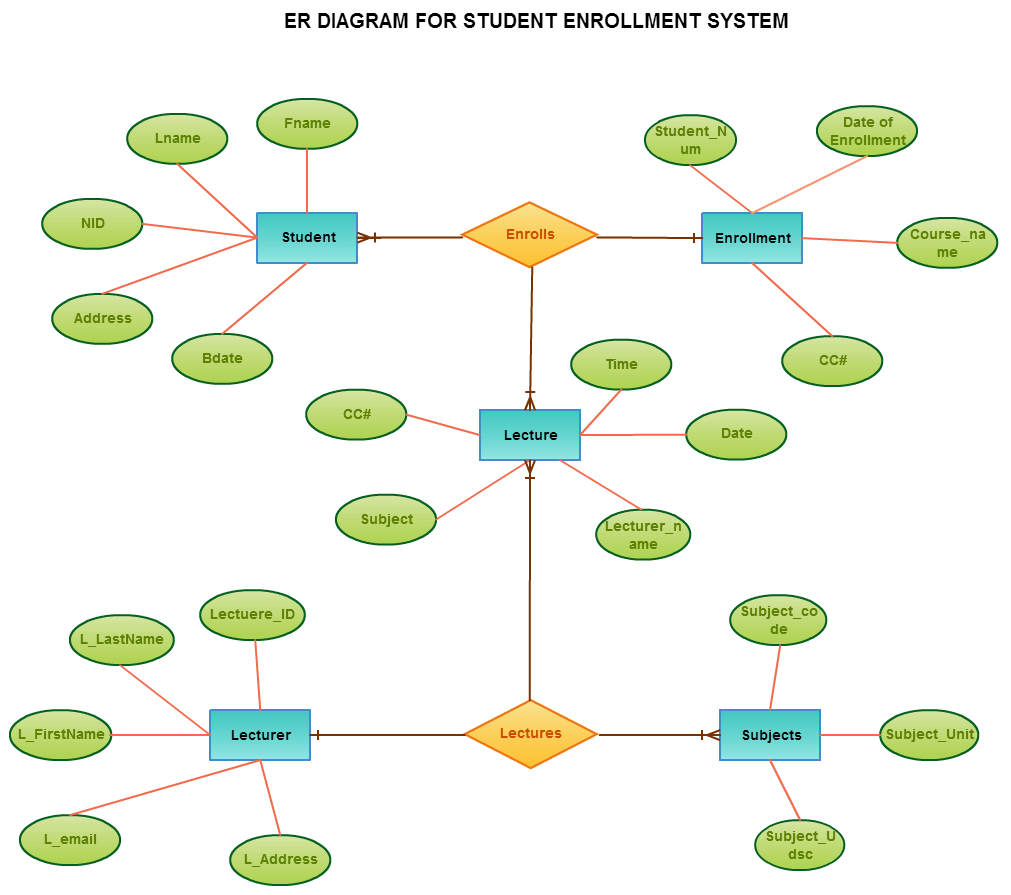
E-R Diagram – Student Management system


E-R (Entity-Relationship) Diagram is used to represents the relationship between entities in a table. ER diagrams represent the logical structure of databases. ER Diagram represent relationship between two database tables.

E-R diagram means Entity Relationship diagram. Entity is a object of system, generally we refer entity as database table , the e-r diagram represent the relationship between each table of database. E-R diagram represent entity with attributes, attributes is a properties of entity. If we assume entity is a database table then all the columns of table are treat as attributes.
ER Diagram
Entity : Entities are represented by rectangle. All table of database are treat as entity.
Er Diagram For College Management System Pdf Download
Attributes : Attributes are represented by ellipses. Attributes are properties of entities.
ER Diagram Symbols
Er Diagram For College Management System Pdf Free

Er Diagram For College Management System Pdf
ER Diagram – Student Management System
